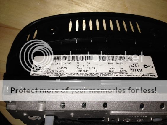
On-board Monitor (CID) 8.8” – 65 82 9 193 745

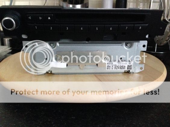
 CIC Head
Unit – 9 214 945
 Connecting Lead, CIC/CID – 61 11 9 185 171
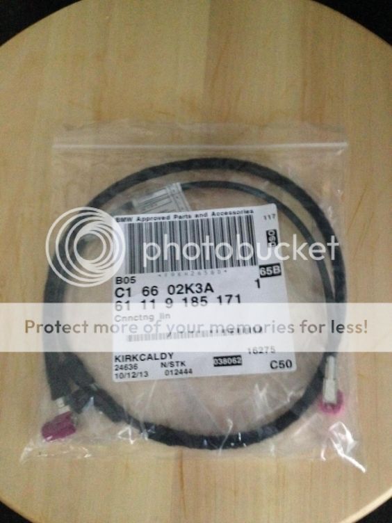
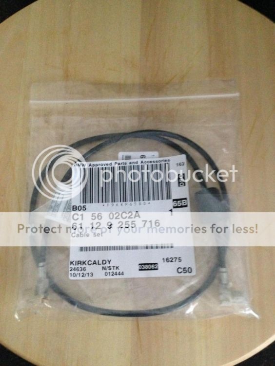
Cable set, USB – 61 12 9 255 716
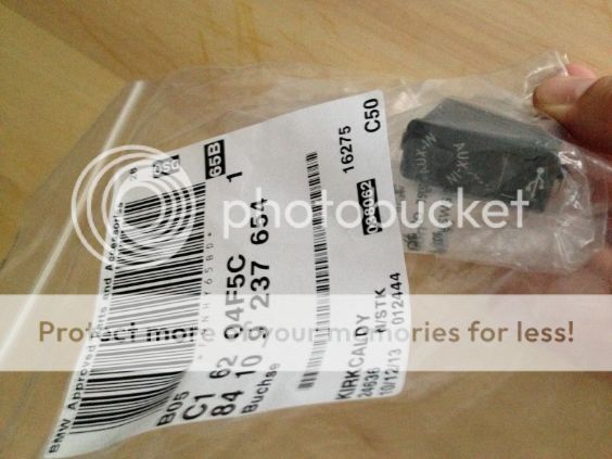
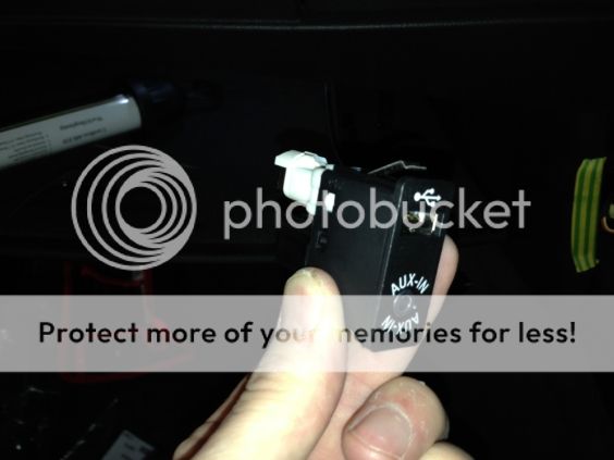
USB/AUX-IN jack, switchable – 84 10 9 237 654 (This isn’t the correct one I need for the CIC USB but I got it anyway as I will need it for when I do the 6FL COMBOX retrofit and I will put it in the armrest) The correct one for the CIC is a USB only as the CIC USB can only be used to load music and update maps.
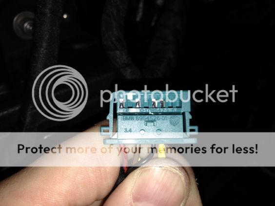
 Universal Socket Housing uncoded 8 POL – 61 13 6 954 526 (This is needed as the 6.5” screen is connected differently to the 8.8”, more in Step 11).
 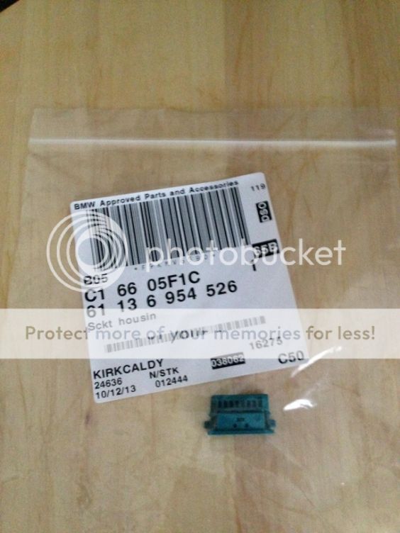 Idrive controller – 65 82 9 189048 (This came with the kit I bought but I didn’t need it as I already had this model fitted so there is no guide for fitting this here, sorry). If you don’t have this controller then the older style will still work but I recommend using this one as it is much easier and more beneficial.
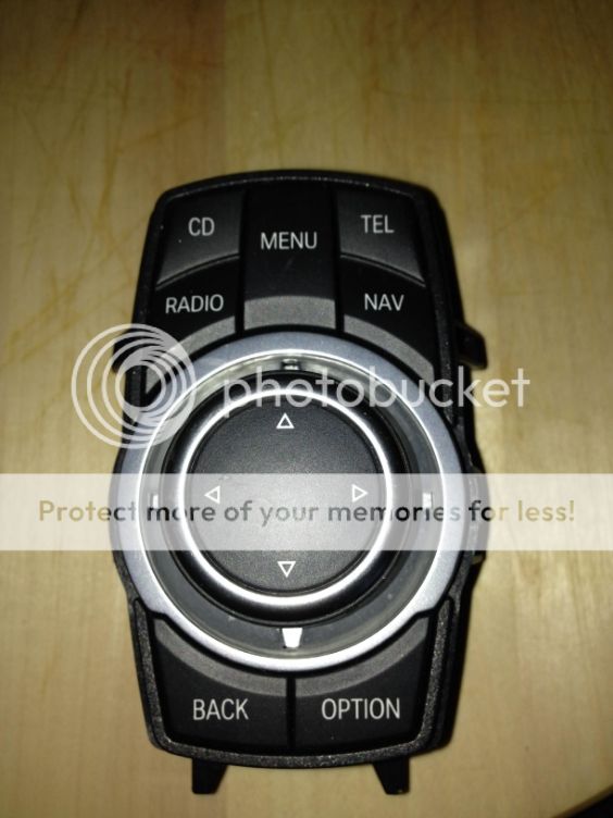
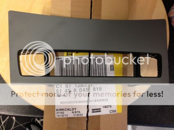
Cover Dashboard, centre – 51 45 8 045 816 (This is the Part No if you have the Alu Pentan trim which is the finish in my car, please check what is correct for yours). You will lose the cubby hole that is below the radio control panel.
new BMW K+DCAN cable and NCS EXPERT software to code the unit to the car.

Tools required: 1 small flat blade screwdriver 1 philips screwdriver 1 trim prying tool (I used the flat blade of a small hammer, see step 2) 1 Torx bit, size 10.
It is advisable but not essential to disconnect the battery to prevent any shorting and fuses blowing when you replace the CID plug in Step 11.
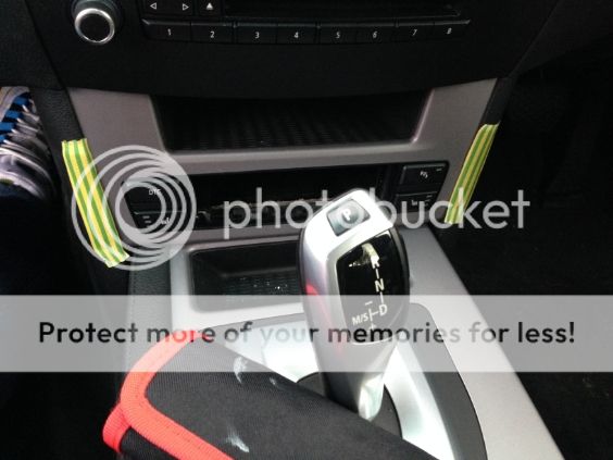
Step 1 Place some tape along edges where you are required to pull trim apart in order to protect the leather.
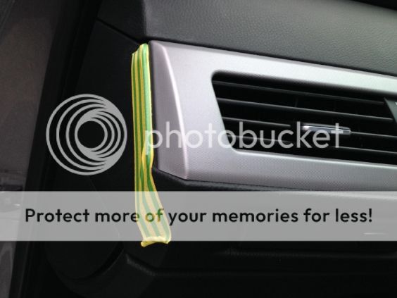
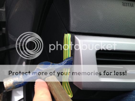
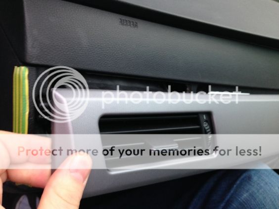
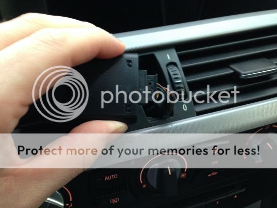
Step 2 Carefully pry the edge of the decorative trim towards the rear of the car. Work along the strip towards the steering wheel and prise all 5 lugs to release the strip.
Step 3 Push the silver clips on the rear of the Hazard light/door lock switch to release it from the trim and remove the plug and switch.


Step 4 Undo the 2 Philips screws (arrowed) and pull the heater controls towards the rear of the car slowly, there are two lugs on the bottom of the trim. Pull out the 2 plugs and remove the heater control facia.
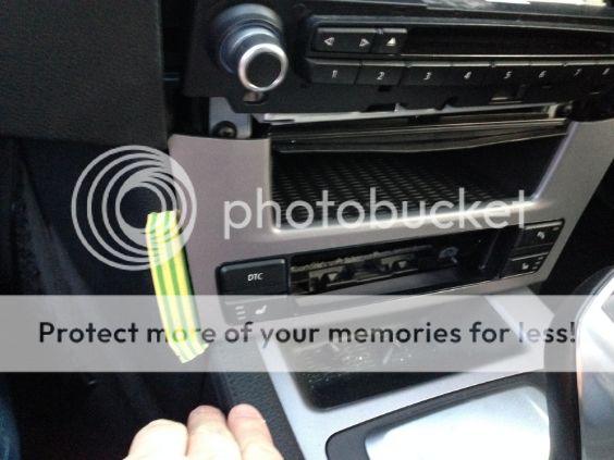
Step 5 Pull the cubby hole trim towards the rear of the car and unplug the supply to the PDC, Heated seats and DTC (2 plugs). Please note the ashtray is already removed in this photo as I forgot to take a photo first time so put the trim back on to take a photo.
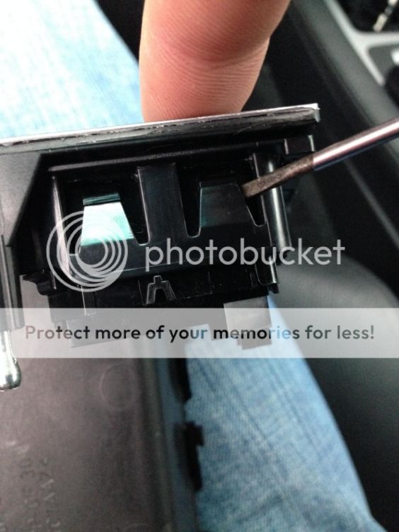
Using a small flat blade screwdriver gently lift the 4 catches individually whilst pushing the switch from the front of the trim to the rear. Do this for both switches.
Step 6 To give more room for movement remove the ashtray by undoing the 2 holding screws (arrowed) and unplugging the rear plug/socket.

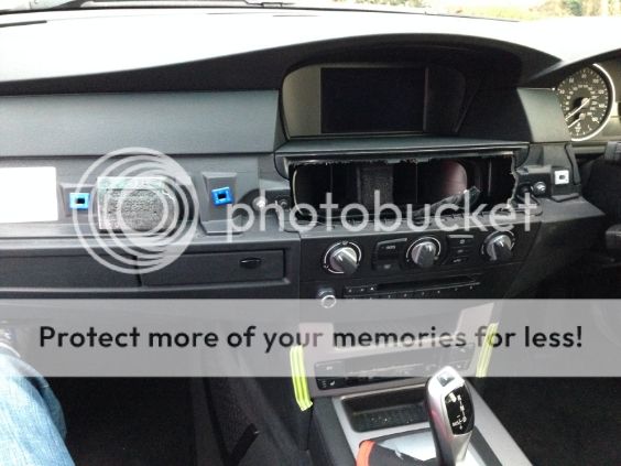
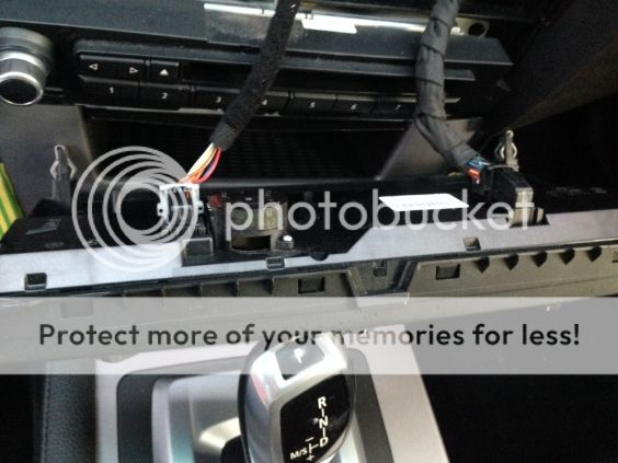
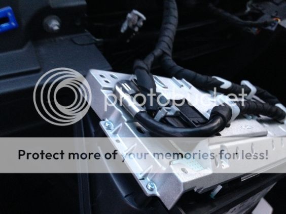
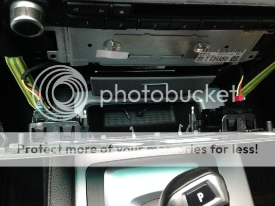
Step 7 Remove the 2 screws (arrowed) that hold the HU in place.
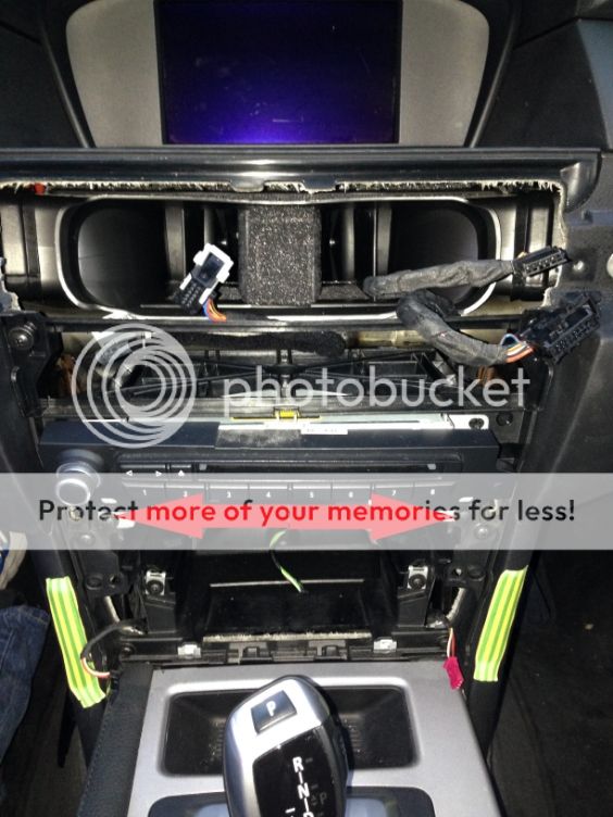
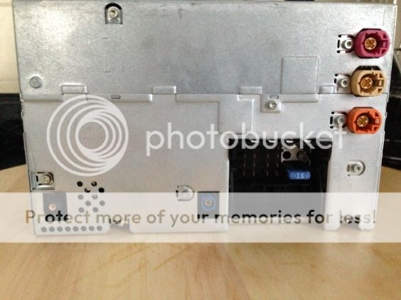
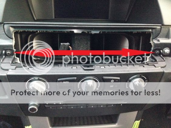
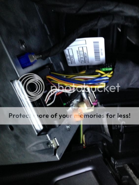
Step 8 Carefully pull HU rearwards and unplug Screen(silver), GPS (Blue), Antenna (black) and main (Big Black) plugs. This main plug is the same as the one fitted to the CIC so will be re-used, whereas on the CCC retrofit it has to be changed.

Step 9 Remove the two screws (arrowed) holding the screen in using a size 10 torx bit.

Carefully pull the top of the screen down slightly and pull the screen rearwards. Remove the display lead and power cable.

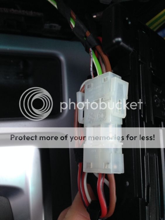
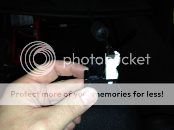
Step 10 The plug needs to be taken apart to reveal the pins in order to fit the new plug. Using a small flat blade screwdriver or point, slightly pry the parts of the plug apart and remove the inner plug.
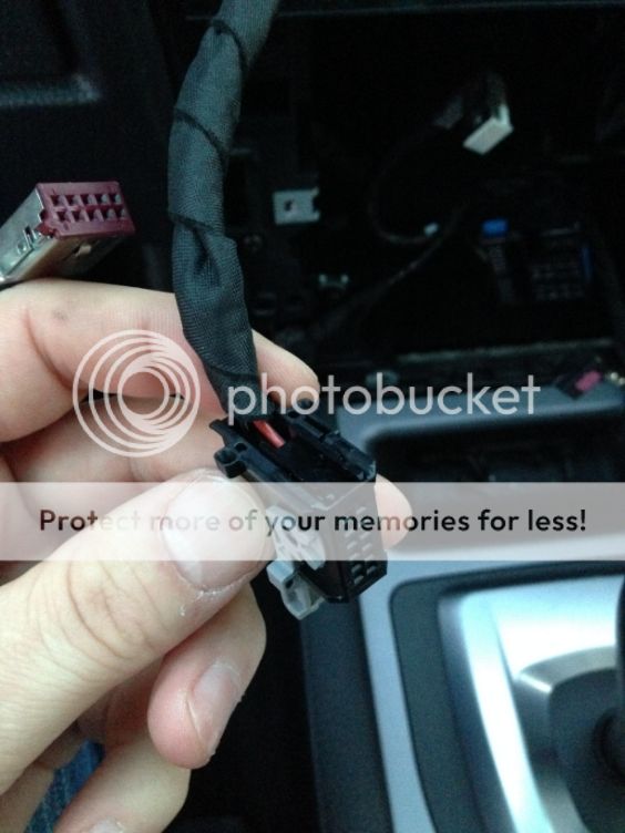
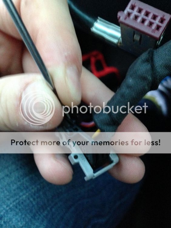
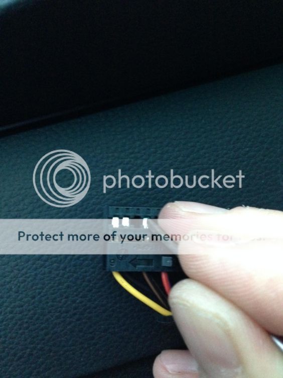
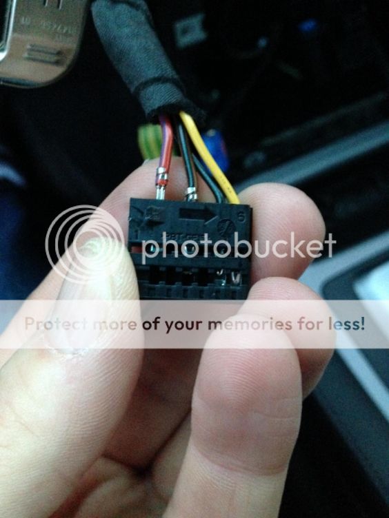
Step 11 Remove the pins using a small screwdriver to press down and push back, they may get caught on the back of the plug and will need to be pressed again. Insert pins into the new plug using pins 1 (Red), 3 (Brown/Black),5 (Black),6 (Yellow). This is why it is recommended to disconnect the battery as my pins touched and blew a fuse.
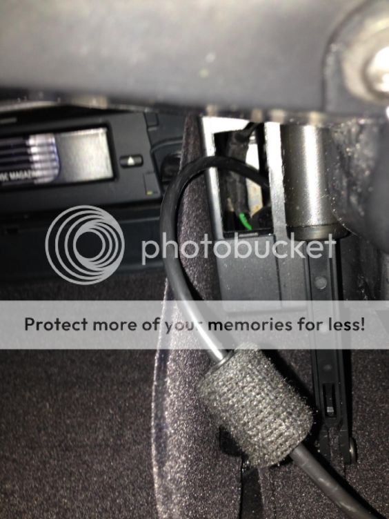
Step 12 Route the new CID cable from the screen aperture down to the CIC HU aperture via the “passage” to the passenger’s side. The darker of the 2 connectors is to be at the top as this end has the extra padding/protection around the cable. Plug cable and power plug into the screen, fold the old screen connector out of the way and reinsert the screen and do up the 2 holding screws.

Step 13 In order to fit the USB socket and cable it is best to remove the glovebox by undoing the Philips screws holding it in at the top and the 4 on the bottom of the glovebox at the top of the footwell where it meets the plastic trim. I didn’t take it right out as I managed to get the cable round and through the hole. Pop out the blanking plate on the right hand side of the glovebox and feed the new USB cable through. Plug in and push the USB into the slot. The USB/AUX socket pictured is not the correct one for the job as explained earlier. Here you only need the USB socket not AUX. Refit glovebox.

Step 14 Connect all plugs to the back of the CIC unit. Blue = GPS Black = AM/FM Antenna Purple = Screen/CID Cream – USB Main plug
Step 15 Slowly push the CIC into to hole ensuring that all cables are pushed out of the way and then screw back in using the 2 screw holes where the MASK was secured.
It is best to test that there is power and the screen comes on at this point, so reconnect the battery if you had disconnected it. I had radio but no screen when I did this. I had popped fuse 79 in the boot space fuse panel after allowing the pins to come into contact during step 11. Replaced the fuse and it powered up. As expected the Navigation was greyed out but all other functions were available, even the music stored on the hard drive.
Now with the CIC in place and proven it is time to start putting everything back together.
Step 16 Refit the ashtray

Step 17 Take the new trim and refit the switches that were removed from the old cubby hold trim by gently pushing them into the slots. Plug in and fit the trim using the locating lugs. Note the loss of the cubby hole.


Step 18 Reconnect the plugs for the heater control panel and refit ensuring the 2 Philips screws are nipped up, not too tight or it will crack the plastic.

Step 19 Pass the hazard plug through the hole in the decorative trim and replace the trim. Plug in the hazard switch and push into place.


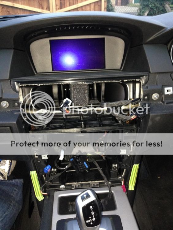
The only visible physical differences between the two systems is the Screen size and the cubby hole.
Step 20 Now get coding. all instructions i get from :http://chasenengineer.blogspot.com/2016/06/bmw-cic-retrofit-coding-using-kdcan.html This is a simple task and can be done by someone with basic hand tools skills i.e. plugs and screws. All in all it took 2-2 ½ hours comfortably.
Save Save
No comments:
Post a Comment